How to build a satellite link budget that actually closes
The full downlink chain (EIRP, back-off loss, FSPL, ITU-R P.618 rain fade, G/T, C/N0, Eb/N0) with a worked 8.2 GHz X-band CubeSat example.

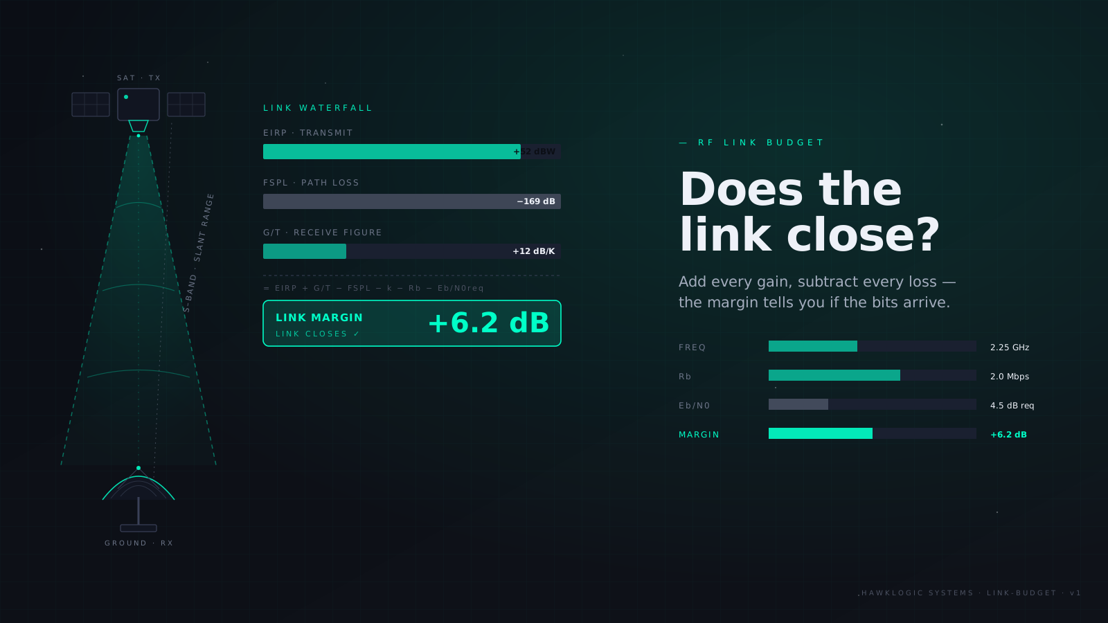
A link budget is an energy audit. You start with the watts leaving your power amplifier, subtract every loss between the spacecraft and the demodulator on the ground, and check whether what’s left clears the receiver’s threshold with margin to spare. Every term is either a gain or a loss in decibels, so the whole thing collapses to addition. The hard part isn’t the arithmetic. It’s knowing which terms exist, which ones people forget, and what realistic numbers look like.
This post walks the full chain for a Low Earth Orbit (LEO) downlink, then runs a worked X-band CubeSat example end to end. If you’d rather have the arithmetic done for you, our link-budget calculator implements everything below, including the terms that most free calculators skip.
The chain in one line
C/N0 [dB-Hz] = EIRP − FSPL − L_atm − L_misc + G/T + 228.6The +228.6 is −10·log10(k), Boltzmann’s constant expressed in dBW/(Hz·K). Everything else in this post is unpacking those six terms.
EIRP: what actually leaves the spacecraft
Effective Isotropic Radiated Power (EIRP) is the transmit power that matters, referenced to an ideal isotropic radiator:
EIRP [dBW] = P_tx [dBW] − back-off loss − line losses + G_tx [dBi]P_tx is the saturated output of your power amplifier. Line losses cover the coax or stripline run between the amplifier and the antenna, plus any switch, diplexer, or isolator in the path. On a CubeSat this is short, but 0.5 to 1.5 dB is typical once connectors are counted. G_tx is the antenna gain toward the ground station, not boresight gain, unless you can guarantee pointing.
Back-off loss, and why it exists
This term gets skipped in most tutorials, which is odd, because it can be the largest single line item you control.
A power amplifier (PA), solid-state (SSPA) or travelling-wave tube (TWTA), is only efficient near saturation, and near saturation it is strongly nonlinear. Its gain compresses (AM/AM distortion) and its phase shifts with input amplitude (AM/PM distortion). Feed a constant-envelope waveform like Gaussian Minimum Shift Keying (GMSK) through a saturated PA and nothing bad happens: the envelope never varies, so the nonlinearity has nothing to distort. Feed it a filtered, amplitude-varying waveform (anything with a non-trivial peak-to-average power ratio) and the PA smears the constellation and regrows spectral sidelobes into your neighbours’ bands.
The fix is to retreat from saturation. Input back-off (IBO) is how far you reduce drive; output back-off (OBO) is how far the delivered power drops as a result. OBO is what enters the link budget, as a direct subtraction from transmit power. Typical values:
| Modulation | Envelope behaviour | Typical OBO |
|---|---|---|
| GMSK, unfiltered OQPSK | Near-constant | 0–0.5 dB |
| Filtered QPSK/OQPSK | Modest ripple | 0.5–1 dB |
| 8PSK | Moderate | 1–2 dB |
| 16APSK | Multi-ring | 2–3 dB |
| 32APSK | Multi-ring, dense | 3–4.5 dB |
The trap: a datasheet says “2 W transmitter”, you budget 33 dBm, then the comms engineer picks 16APSK to hit a data-rate target and quietly loses 2.5 dB of it. Nobody updates the budget. The link closes on paper and fails at 5° elevation in the rain. Put back-off in the budget as its own line, from day one, tied to the modulation choice.
FSPL: the big number
Free-Space Path Loss (FSPL) is spreading loss, the inverse-square law expressed in dB:
FSPL [dB] = 92.45 + 20·log10(f [GHz]) + 20·log10(d [km])The distance is slant range, not altitude. At low elevation angles the geometry punishes you: for a 550 km orbit, range is 550 km at zenith but about 2205 km at 5° elevation. That’s 12 dB of swing across a single pass. Size the link at your minimum operating elevation, because that’s where you’ll actually be commanding the spacecraft when it matters.
Slant range for elevation ε and altitude h, with Earth radius Re = 6371 km:
d = √((Re + h)² − Re²·cos²ε) − Re·sinεAtmospheric and rain losses: ITU-R P.618
Between vacuum and the dish sits the troposphere. Three effects matter at microwave frequencies, and the ITU-R P.618 recommendation is the standard prediction framework for all of them:
- Gaseous absorption (oxygen and water vapour, ITU-R P.676). Small at X-band: roughly 0.2–0.5 dB at low elevation. It grows sharply near the 22 GHz water line and the 60 GHz oxygen complex.
- Rain attenuation. The dominant statistical loss above ~5 GHz. P.618 predicts the attenuation exceeded for a given percentage of an average year from the local rainfall rate exceeded 0.01% of the time (R0.01, from ITU-R P.837 maps), an effective path length through the rain cell, and frequency-dependent regression coefficients. Attenuation rises steeply with frequency: a rain event that costs 1 dB at X-band costs several dB at Ka. The knob you control is availability: designing for 99.9% instead of 99.5% can add multiple dB of required margin, so decide what an outage actually costs your mission before buying margin against it.
- Scintillation and cloud attenuation. Usually fractions of a dB at X-band; they matter at Ka/Q and at very low elevations.
Add two miscellaneous terms while you’re here: polarization mismatch loss (0.1–0.5 dB for circular-to-circular with realistic axial ratios) and pointing loss on both ends (a ground antenna tracking 0.1 beamwidths off costs ~0.1 dB; a body-pointed CubeSat antenna a few degrees off its beam centre can cost much more: check your antenna pattern against your Attitude Determination and Control System (ADCS) pointing spec).
G/T: the ground station in one number
The receive system is characterised by its figure of merit G/T: antenna gain divided by system noise temperature, in dB/K. Gain follows aperture; noise temperature Tsys sums the antenna noise (ground spillover, atmosphere, cosmic background), feed losses, and the Low-Noise Amplifier (LNA). A 3.7 m dish at 8.2 GHz delivers roughly 48 dBi at 65% efficiency; with Tsys ≈ 200 K at low elevation, G/T ≈ 25 dB/K. Commercial ground segment providers publish this number per station. Note that Tsys degrades at low elevation (the beam sees more warm atmosphere), so the quoted G/T should be for the elevation you’re budgeting at.
From C/N0 to margin
With carrier-to-noise-density C/N0 in hand, divide by the data rate to get energy per bit over noise density:
Eb/N0 [dB] = C/N0 [dB-Hz] − 10·log10(Rb [bit/s])Compare against the required Eb/N0 for your modulation and coding at the target Bit Error Rate (BER). A Consultative Committee for Space Data Systems (CCSDS) rate-1/2 Low-Density Parity-Check (LDPC) code on QPSK needs about 2 dB; the older concatenated convolutional + Reed–Solomon standard needs closer to 3. Then subtract implementation loss (1–2 dB for demodulator imperfections, phase noise, imperfect synchronisation) and what’s left is margin.
The rule of thumb is a minimum of 3 dB of margin at worst-case geometry and availability. Less than that and normal hardware ageing, antenna pattern ripple, and model error will eat you.
Worked example: 8.2 GHz X-band CubeSat downlink
A 6U CubeSat at 550 km, X-band payload downlink at 8.2 GHz, 25 Mbps, filtered OQPSK with CCSDS rate-1/2 LDPC, sized at 5° elevation. You can reproduce this run in the calculator and perturb any line.
| Term | Value | Note |
|---|---|---|
| PA saturated power | +3.0 dBW | 2 W SSPA |
| Output back-off | −1.0 dB | filtered OQPSK |
| Line losses | −1.0 dB | coax + isolator + connectors |
| TX antenna gain | +6.0 dBi | X-band patch |
| EIRP | +7.0 dBW | |
| FSPL | −177.6 dB | 2205 km slant, 8.2 GHz |
| Gaseous absorption | −0.3 dB | P.676, 5° elevation |
| Rain (99.5% avail.) | −1.0 dB | P.618, temperate site |
| Polarization loss | −0.2 dB | RHCP both ends |
| Pointing loss | −0.5 dB | both ends |
| G/T | +25.0 dB/K | 3.7 m dish, T_sys ≈ 200 K |
| −10·log10(k) | +228.6 | Boltzmann |
| C/N0 | 81.0 dB-Hz | |
| Data rate (25 Mbps) | −74.0 dB | |
| Eb/N0 achieved | 7.0 dB | |
| Required Eb/N0 | −2.0 dB | LDPC 1/2, QPSK |
| Implementation loss | −1.5 dB | |
| Margin | +3.5 dB | closes |
The link closes with 3.5 dB. Notice what dominates: FSPL is fixed by geometry, G/T is fixed by whose ground network you bought, and the terms you actually control (back-off, antenna gain, data rate) live within a few dB of each other. Halving the data rate buys exactly 3 dB. That’s often the cheapest margin on the sheet.
The check nobody does: does the rate serve the mission?
A closed link at 25 Mbps is useless if the payload generates 400 Gbit per day and you get eleven minutes of cumulative pass time. Before locking the RF design, run the volume side: instrument duty cycle, onboard storage, passes per day at your chosen station latitude, usable minutes per pass above your minimum elevation. Our data-budget tool does this accounting and will tell you whether the downlink and the payload are even having the same conversation.
Two failure modes show up constantly in review. First, the budget that closes at zenith and is never re-run at the elevation mask. Second, the budget with a “misc losses: 1 dB” line that silently absorbs back-off, pointing, and polarization all at once, each of which deserves its own number and its own owner. A link budget is a contract between subsystems. Write every clause down.
On this page
Read next
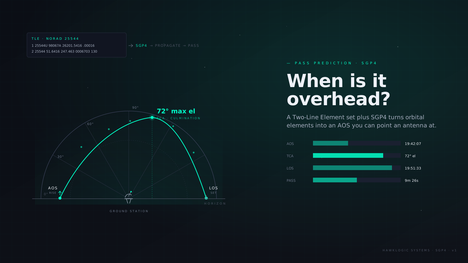
When is my satellite overhead? TLEs, SGP4, and pass prediction
How a Two-Line Element set and the SGP4 propagator become ground-station pass windows (AOS, LOS, elevation masks, max elevation) and why TLE freshness is the whole accuracy story.
7 min read
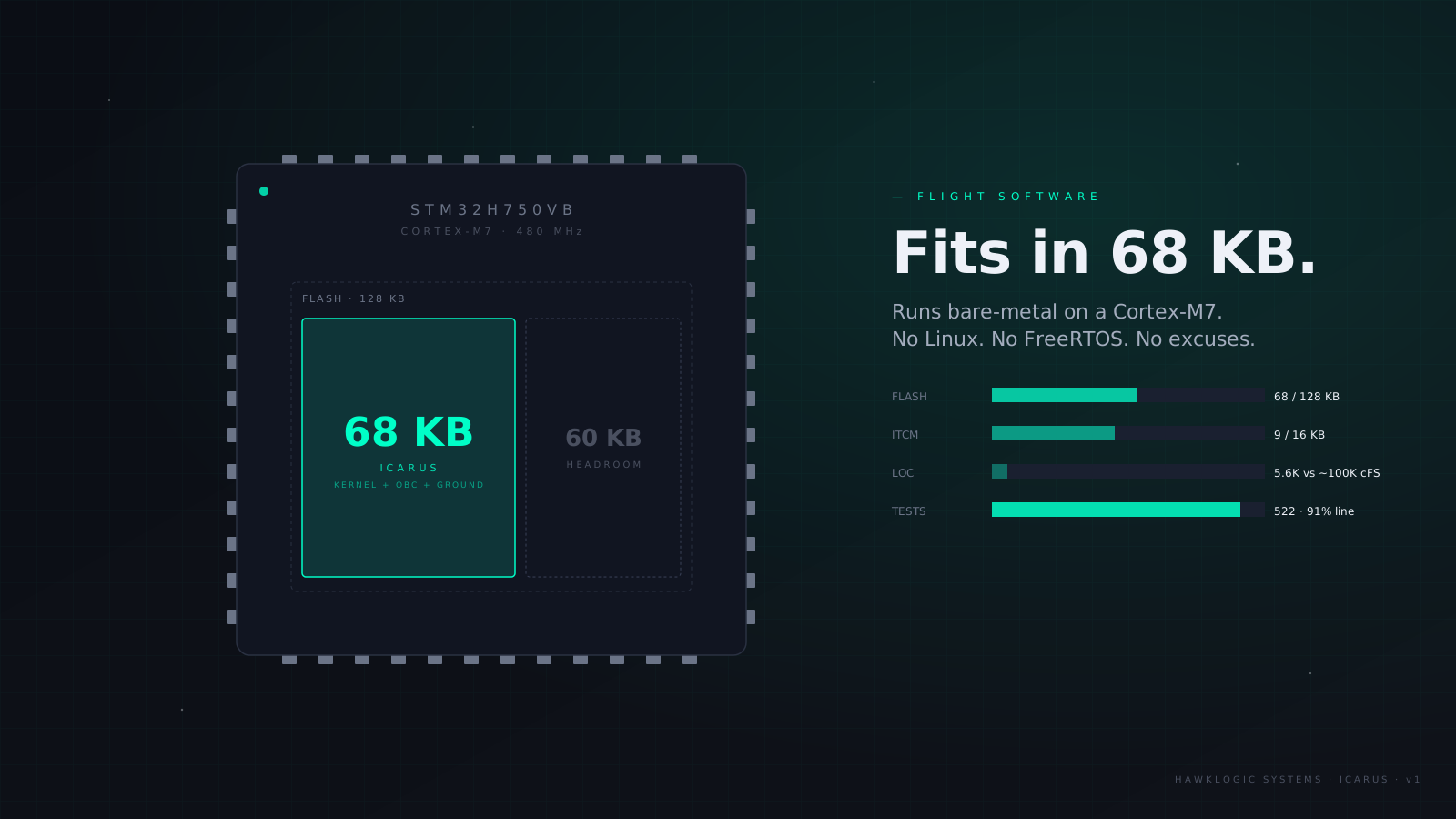
How we fit a satellite flight computer in 68 KB of flash
ICARUS, our satellite OBC platform, runs the full stack (kernel + OBC app + ground-link protocols) in 68 KB of flash on a Cortex-M7. No Linux. No FreeRTOS. Here's why, and what it cost us to get here.
8 min read